
Blog
How to Wire a 12 volt Linear Actuator
How to Wire a 12 volt Linear Actuator
The simplest and most efficient way to control your electric actuators is with a rocker switch. The rocker switch role is to manage how you actuator extends and retracts. The options available for rocker switches include momentary and non-momentary.
Momentary (latching) switch
The momentary rocker switch extends and retracts when a button is pressed. Once you release the button, the movement stops.
Non-momentary (non-latching)
The non-momentary switch has three different states; extend, retract and off. When you need to stop the actuator, you’ll need to press the rocker switch to an ‘off’ position.
Wiring two parts together can be tricky if you have no experience or idea. You, however, are in the right place as we are going to show you how to easily wire your linear actuator in simple steps.
What you require before you start
- A power source – you can either use a 12v DC battery or a 110/220V AC power adapter NOTE: Make sure that your selected battery or power adapter has the correct amperage to power your actuator
- linear actuator
- Rocker switch
- Wiring kit – can contain 12m Molex connector, in-line fuse(2 fuse holders with fuses), 2 limit switches and 2 diodes
- Wire strippers
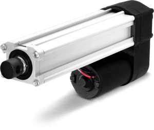
The 12v actuator has an efficient operating capacity compared to the 24v actuator. They are ideal when you are tight on space and don’t weight much. Also known as mini actuators, they can range from 35, 50 to 150lbs with strokes of 1-40 inches and with speeds of 0.60-2inches/second.
The in-line fuse consists of a fuse holder designed to fit a fuse. The fuse holder’s main aim is preventing damage in the system caused by power spikes; this is because the unit is enclosed. It is vital to have the correct amperage for the actuator’s operation, which is 10A. You’ll require an additional to ensure that the fuse holder is suited to work with the particular fuse you have.
The battery aids in power conversion. The two main things you should look for in a power source is reliability and functionality for your specific actuator. A control box converts AC to DC to be used in the home setting. The control box can be wired or used a wireless remote control depending on which model you are using. The power source works simultaneously or non-simultaneously to either control a single or multiple actuators.
The Molex connector is an integral part of the wiring process as it helps to link the strokes to aid the connected wires long enough to reach the motor.
Before jumping in, let’s take a look at the various parts of a rocker switch. The switch has a couple of terminals namely:
- T1- which is connected to the battery’s positive terminal depicted as (+)
- T2- this is the second actuator terminal and its depicted (black)
- T3-this is the battery’s negative terminal depicted as (-)
- T4-this is the battery’s negative terminal depicted as (-)
- T5-this is the actuator’s terminal depicted (red)
- T6-This is the battery’s positive terminal (+)
The Wiring Process
The first process is to prepare the two wires by cutting them ensuring that they are long enough to reach the battery. The two wires to be joined to the actuator should be loose.
The first wiring procedure is simple. There are two connectors at the center namely T2 and T5 and are the common connectors in this scenario. To operate the linear actuator with a rocker switch, we need to start the wiring process. The procedure requires only three simple steps.
- The T3 and T4 connectors go to the (-) terminal also known as (GND) of the power supply
- The T1 and the T6 connectors go to the (+)(12v) terminal of the power supply
- The T2 and T5 connectors go to the linear actuator wires
Once you’ve set up everything and a connection is obtained, you are now ready to switch your 12v to the linear actuator extending it. Turning the switch to the off position, the actuator retracts.
The next wiring procedure uses a push-button rocker switch that requires wiring. It contains two switches with one having a NO (Normally Open) and NC (Normally Closed). In this particular connection, a 12v LED is included that lets you know everything is ok and there’s no fault.
This type of switch has a lower current limit. It’s recommended that you use a relay if you are controlling more than 2A. The focus right now is on the rocker switch.
The operation of this switch is when the button is pressed the actuator extends and then retracts when released. This switch has addition connectors, the T7 and T8. Below are the steps to follow when wiring your actuator:
- The T1 and T7 connectors go to the (-) terminal or the (GND) to the power supply unit
- The T3 and T5 connectors go to the (+) terminal (12v) on the power supply
- The T2 and T4 connectors go to one actuator wire
- The T6 and T8 connectors go to the other actuator wire
Joystick
We then have the joystick, which has four NO (Normally Open) switches. Just to give you an example, when you move the joystick to the right, the right switch closes and the same happens when you move it on the opposite direction.
A joystick can be used to control different kinds of actuator movements. We are going to show you how you can connect two actuators one to control right and left the movement and the other down and up.
When you move the joystick to the left actuator, it will extend and when moved to the right it will. When you move the joystick to the second actuator, it extends and when you move it down it retracts. The joystick is in a neutral position when it’s at the middle and the actuators don’t move.
3-way toggle switch
The scenario is wiring your actuator to a 3-way toggle switch. Start connecting the red wires. You should connect them diagonally from each other, in simpler terms think of it as a back slash or forward slash. The next set of wires is your black wire keeping in mind the same configuration (diagonally as the red wires) should be on the opposite side. (Remember to screw them firmly in place)
Connect the ends of the two red wires together. Connect the two back wire ends together. Connect a long red wire to the end of the red wires you have just connected. Similarly, do the same for the black wire tapping the naked wires connected together. This also applies to the red wire.
Now it’s time to wire the switch connectors in the middle. For this, you will require two yellow wires. Connect the yellow wires to the middle of the switch. Make sure the wires don’t make contact with the red or back wires otherwise you’ll have a fire. The yellow wires are then connected to your battery
Take the positive and negative wires of the actuator red and black wires respectively and connect it to the positive and negative connection on your three-way toggle switch.
In all of the above scenarios, your rocker switch will facilitate your actuator’s movement. Your linear actuator should now be able to be controlled by your switch. It’s vital to test to make sure everything is connected properly.
As you have read, it’s not complicated to wire your linear actuator for your next project. All you need to do is select the actuator that is suitable for your project and get the necessary parts to connect,
If you have no clue how to make your pick, you can always consult a registered and authorized distributor or manufacturer. To find them, you have many tools online that include reviews and the number of sales made.
Seek consultation from their experienced stuff about how best to wire your actuator and what’s exactly needed to make your project flourish. This is important because it will give you a clearer picture of what you are going to embark on and point you in the right direction.
They can also help you pick the best wiring kits and aids that will suite you project. Keeping in mind that, you’ll be armed with knowledge and not make mistakes that could have been prevented.
Finally…
Before starting to embark on wiring your actuator, you need to ensure that you have all the necessary parts, your linear actuator meets your project needs and your power source amperage is adequate.
Do not by any chance let different wires touch each other as this could cause fires. Make your connection first and then embark on testing. Never be quick to test on the go. A good way to make sure you have achieved the correct connection is by using LEDs. They aren’t costly and are efficient in testing. Make sure your power source is only connected after you have finished connecting and remember to disconnect afterwards.